
Unified Modeling Language: A techies Creative Expression

Hello Readers!
Welcome to another article where we discuss major concepts that are useful in the technological and digital spaces.
Today, we’re going to learn an important concept that cuts across all tech professions. This concept is called the Unified modeling Language.
As a creative, your greatest tool is your mind, where the colorful idea is generated, then whether it is via your voice, a paint brush or a pencil, whatever channel it may be, you let it out into the world.
Most of the time this is a spontaneous process for them as the best art comes from the place of emotions and deep feelings. This process is what most of the greats make use of that leads to the beautiful masterpiece we may have come across at one point in our life or the other.
For us in the tech space, the process is a bit similar, with just an extra step to it.
Like the artist, we have a mind that generates beautiful ideas, and like the artists we have a channel in which we let the ideas into the world to be experienced by many.
However, unlike the artist we do not let ideas into the world spontaneously because tech requires logic and logic on the under hand requires clarity. In order to gain clarity in the tech space an extra step is introduced, Modeling.
Modeling is the process of creating a representation of something, such as a physical object, a system, or a process.
It can be used to understand how things work, predict how they will behave, or design new things. Modeling is an extra layer on our landscape that gives us the clarity we need before we introduce our great ideas in their functional form to the world.
Most techies are likely to work in teams, so when modeling an idea, it must be done so that everyone understands it.
This is why the Unified Modeling Language(UML) is very important, whether you are a product manager, product designer, front-end engineer back-end engineer, cloud engineer, dev ops or so on, UML is one tool in your tool box that would always help you do all the heavy lifting.
This is because, the better you understand a system, the easier it is to implement.
There are two main categories of UML Diagrams
STRUCTURAL DIAGRAMS
Structural diagrams are used to represent the static structure of the system. They show the different elements of the system and how they are related to each other. Structural diagrams are used to understand the system's architecture and to design the system's implementation. They represent the components, relationships, and interactions between various elements of the system.
They further divided into
Class Diagram: Class diagrams represent the static structure of the system by showing classes, their attributes, methods, and relationships with other classes. They depict the overall class hierarchy and associations between classes, such as inheritance, aggregation, composition, and dependencies.
Object Diagram: Object diagrams capture a snapshot of the system's instances at a particular point in time. They provide a concrete view of the system, representing actual objects and their associations.
Component Diagram: Component diagrams illustrate the high-level organization and dependencies between software components. They depict the physical or logical components of a system and their interfaces, relationships, and dependencies. Component diagrams are useful for understanding the system's modular structure and how different components interact.
Composite Structure Diagram: Composite structure diagrams represent the internal structure of a class or component. They show the internal parts of a class or component, their relationships, and their interactions. Composite structure diagrams are used to model complex structures within a single class or component.
Package Diagram: Package diagrams organize classes, components, and other elements into packages, representing higher-level groupings of related elements. They show the dependencies, relationships, and interactions between packages. Package diagrams provide a modular and hierarchical view of the system's organization.
Deployment Diagram: Deployment diagrams illustrate the physical deployment of software components on hardware nodes. They represent the hardware infrastructure, nodes (e.g., servers, computers), and the software components deployed on those nodes. Deployment diagrams show how the software components are distributed across the hardware environment.
BEHAVIORAL DIAGRAMS
Behavioral diagrams are used to visualize the dynamic behavior and interactions of components or objects within a system.
They depict how the system responds to stimuli, processes data, and executes behaviors. The key behavioral diagrams in UML include:Use Case Diagram: Use case diagrams represent the interactions between actors (users, external systems, or entities) and the system. They illustrate the various use cases (actions or operations) that can be performed by actors and how they interact with the system. Use case diagrams help identify system functionalities from a user's perspective.
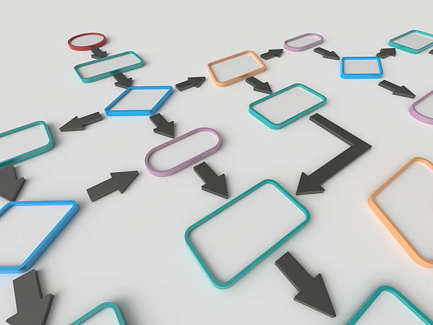
Activity Diagram: Activity diagrams capture the flow of activities or processes within the system. They show the sequence of actions, decision points, concurrency, and control flows. Activity diagrams are useful for modeling business processes, algorithms, or complex system behaviors.
Sequence Diagram: Sequence diagrams represent the interactions between objects or components over time. They show the sequence of messages exchanged between objects, the order of method calls, and the lifelines (object instances) involved in the interactions. Sequence diagrams depict the dynamic behavior of a system during a specific scenario or use case.
State Machine Diagram: State machine diagrams model the behavior of a single object or component as a finite state machine. They represent the different states, transitions, and events that trigger state changes. State machine diagrams are useful for modeling the lifecycle of an object, its state transitions, and the conditions for those transitions.
Communication Diagram: Communication diagrams (previously known as collaboration diagrams) depict the interactions between objects or components. They show the objects or components as nodes and the messages exchanged between them. Communication diagrams emphasize the structural relationships between objects and the flow of messages during a scenario.
Interaction Overview Diagram: Interaction overview diagrams provide a high-level overview of the interactions between components or objects. They combine elements from activity diagrams and sequence diagrams to illustrate the interactions as a series of activities or interactions between objects.
Dear Reader,
Using a combination of these various diagrams, a clear picture of the system is seen, and it is hence a lot easier to implement. Teams can look at them together and make additions to the project even before implementation is started.
This is strongly beneficial to the development of an idea because of the enormous benefits it adds.
Do you have a new project you’re working on?
It would do a lot of good to incorporate this into your next project if you haven’t started yet.